background
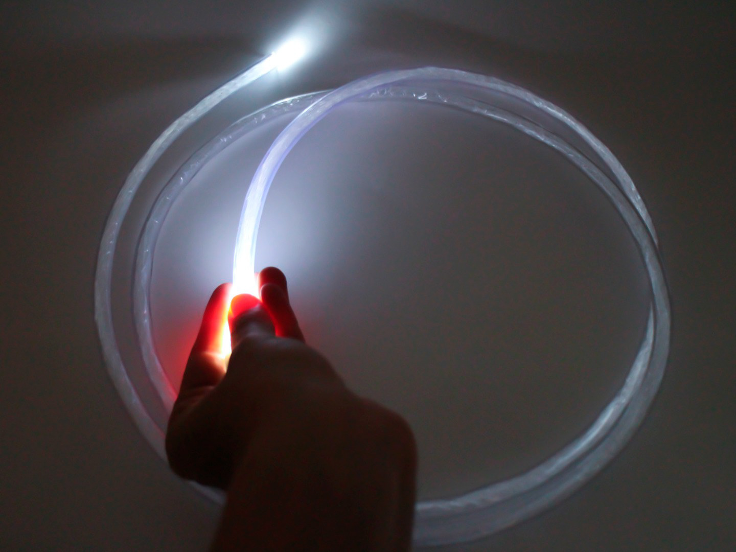
Optical fibers transmit light through thin glass or plastic strands using total internal reflection, enabling high-speed data transfer and dynamic lighting. Beyond telecom and medical uses, it has become a powerful artistic medium, shaping light in space. This project explores optical fiber’s potential to blend and diffuse light from two directions.

materials
• 2,860ft (yes, really) optical fiber, .03" diameter, PMMA end glow
• WS2812B LEDs (5V)
• Meanwell LRS-100-5 power supply (5V)
• Black PLA filament
• Loctite super glue
• UV resin
• 14 AWG power cord (rated for 15A+)
• XIAO ESP32C3
• Basic electrical components (resistors, wire, in-line switch, push button, perfboard)
• Soldering materials
• IKEA NISSEDAL mirror
process
• Sketch out concept → what should it look like? what fabrication steps need to be taken?
• 3D model LED holders → start by measuring LED strip size, then model on Fusion 360
• 3D print LED holders → print off, check fit, adjust model, rinse, repeat
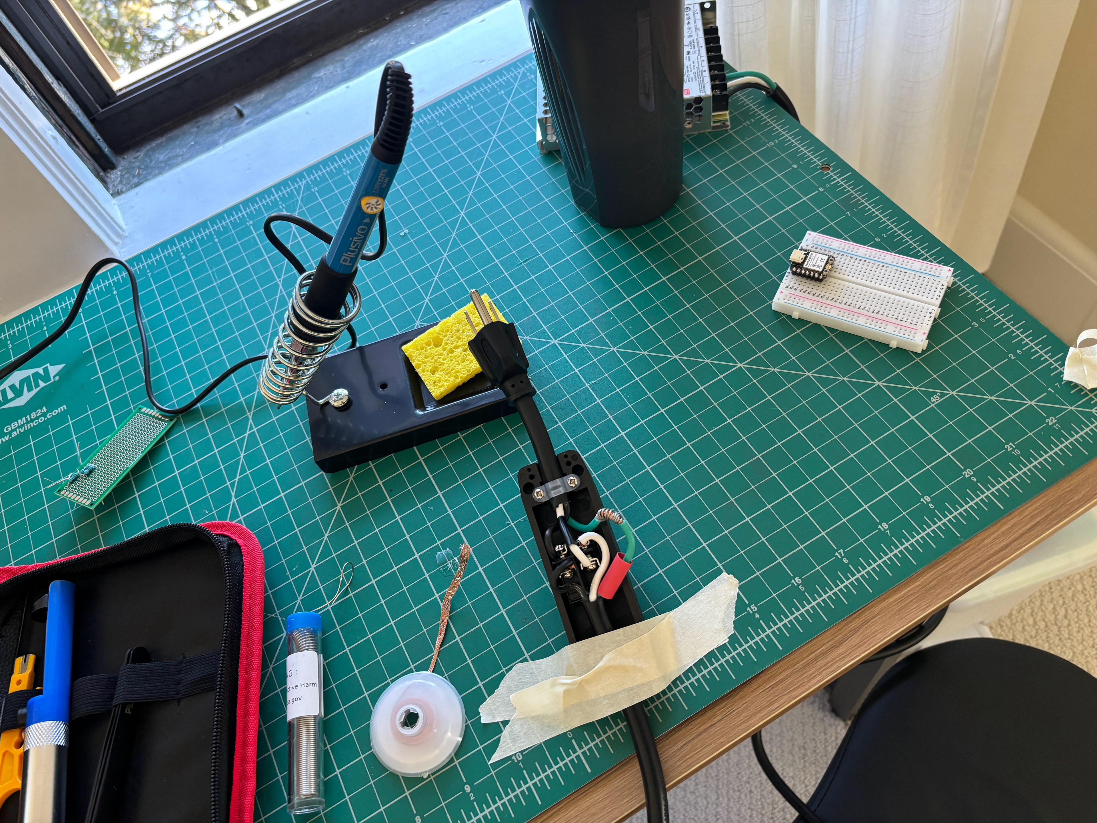
• Create circuit diagram → list out hardware components, verify hardware is supported by libraries (ex. FastLED)
• Solder everything together → burn yourself, inhale lead, desire to have an actual studio space with real ventilation
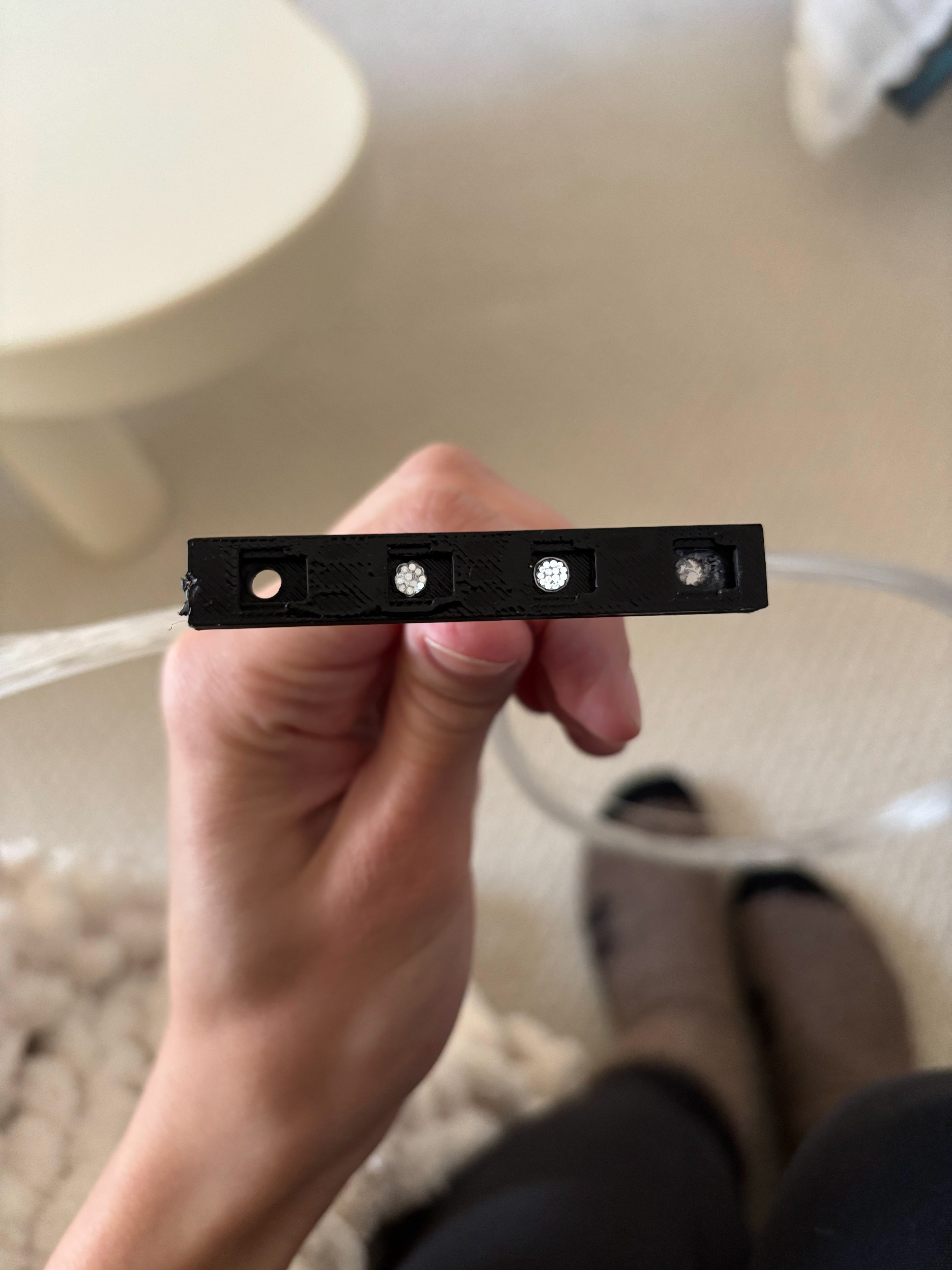
• Secure lights in holders → these models are technically snapfit, but you can make them permanent with superglue
• Secure lights to mirror → superglue your printed parts (with LED strips inside) to edges of mirror
• Create fiber bundles → sand, cut, and group optical fiber bundles into 88 bundles consisting of 15 strands, each 26" long
• Bond fiber bundles → use UV resin to secure fiber bundles to the LEDs housed in the printed parts
• Program modes → the fun part!

sketching
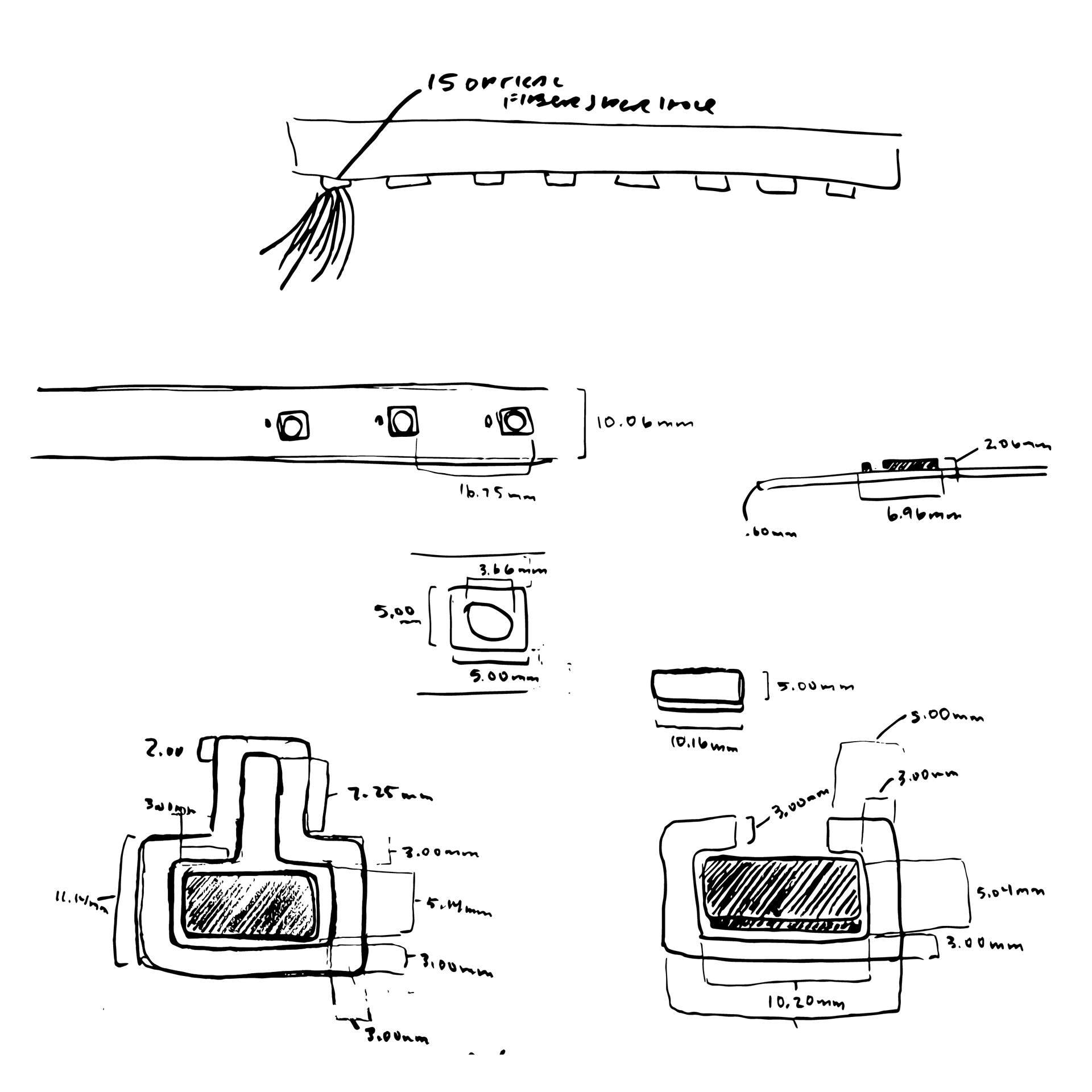
3d printed part diagrams
how optical fibers transmit light
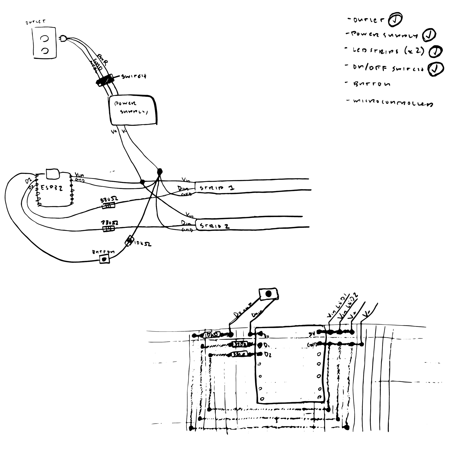
circuit diagrams